Designation. The system is designed for automatic tracking of joint center with V-groove or joint line with a gap close to zero in submerged-arc welding of pipe load bearing welds.
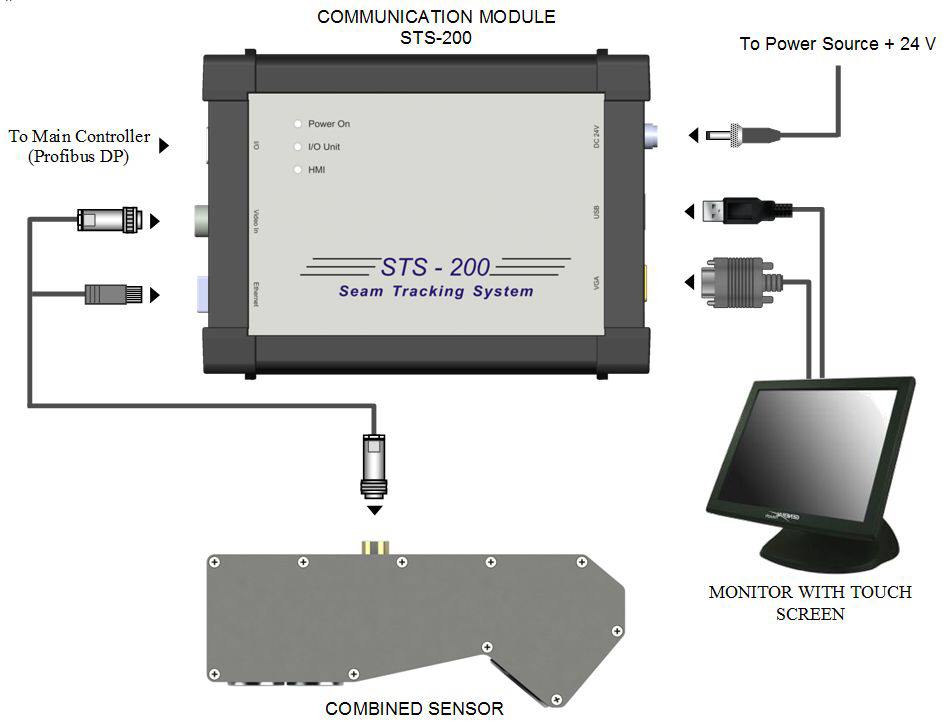
Structure and operation concept. The system consists of three main components, namely special combined sensor; communication module STS-200 and monitor with responsive tough screen (Figure 1). The monitor can be connected using VGA and USB interfaces (USB for sensor screen). Porfibus DP interface is used for interaction with the main controllers of welding unit. The system is supplied from direct current power source + 24V.
There are two modes of system operation:
- tracking a joint with V-groove;
- tracking a joint line with a gap close to zero

In the first mode tracking is based on a laser scanner basic signal. It is 2D joint profile with identified edge points and groove center. The second mode for determination of transverse displacement of the joint line applies the streamed scanned images processed on-line. Switching between the modes of operation and visualizing is carried out with the help of monitor sensor screen. The streamed scanned images if necessary can be used for joint line monitoring at manual tracking. Position of zero markers on the screen can be set automatically on joint current coordinates as well as manually.
The sensor is set before welding head on regular position using bolts.
A mechanism of digital scaling of the laser scanner basic signal almost without loss of input image quality is provided to increase reliability of identification of joints with V- groove of small size. Realized scaling coefficients are 1, 1.5 and 3.
The algorithm was realized for protection of system “deviation” in presence of mechanical or optical interferences, which is based on statistical analysis of previous coordinates of the joint. A special algorithm was also used for suppression of the disturbances appearing because of laser radiation re-reflected from V-groove.
The system has the following operation concept. In the initial moment the system is in waiting mode. A ready-to-track signal is formed after joint identification. The messages in output buffer Profibus DP are constantly renewed. The “deviation” protection algorithm is switched on after system transfer in automatic tracking mode. The system is in “Norm” mode when correct joint coordinates are determined. In the case of the errors of joint identification or activation of “deviation” protection algorithm the system is put in “Failure” mode. If the joint is not identified during a set period of time, then the system is put in “Reject” mode. Depending on settings the system can independently come out from “Reject” mode at stable repeatable detection of the joint or using external commands by means of switching off and then switching on of automatic tracking. After automatic tracking is switched off the system is again put in the wait mode. The information on current state of the system is displayed on-line.
Performance characteristics
| Types of identified joints | V-groove (mode 1) |
| Gap close to zero (mode 2) | |
| Accuracy of joint tracking, mm | ±0,5 |
| Nominal distance from sensor to pipe, mm | 125 |
| Maximum operating area of sensor in transverse direction, mm | ±30 |
| Sensor operating area on vertical line, mm | from 95 to 170 |
| Minimum allowable residual depth of V-groove, mm | 2 |
| Minimum allowable gap in joint line tracking, mm | 0,3 |
| Maximum length of communication line between sensor and communication module, m | 50 |
| Power supply | +24 В |
| Consumed power taking into account monitor, W, not more | 120 |
| Breakdown voltage of sensor galvanic insulation, kV, not less | 1,5 |
| Sensor IP protection | IP64 |
| Operating temperature range, °С | -10..+65 |


